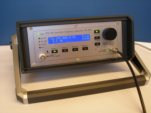
Versatile Frequency Generator VFG 150

Some key features:
- Frequency range: 1-150 MHz
- Waveforms: sine, arbitrary
- Frequency switching modes: phase-continuous, phase-coherent
- USB 2.0 computer interface with streaming capability
- Four additional digital outputs
- All I/O are galvanically isolated
- External reference: 10, 20 or 25 MHz
- Fixed trigger latency
See also Photonics Technologies and vfg-control for more information or contact Christof Wunderlich
What is phase coherent frequency switching?
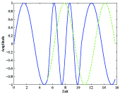
When switching the rf signal of a usual generator from a given frequency ω1 to another frequency ω2, the initial phase of the signal at frequency ω2 is either random (a discontinuity in the rf signal's amplitude occurs), or the signal is switched between frequencies such that the rf amplitude goes on continuously. In the latter case, the initial phase of the rf signal at frequency ω2 is determined by the signal's phase at frequency ω1 at the time of switching. This mode is labelled "phase-continuous switching". In this mode phase-information of frequency ω1 is not preserved when switching between different frequencies. Figure 2.1 shows an example of phase-continuous switching for the frequency cycle ω1 -> ω2 -> ω1 (the frequency is switched at scaled times t=5 and t=10). Here, the green line indicates the phase the signal at ω1 would have, if no switching to ω2 had occurred. As one can see, this phase is not preserved when switching from ω2 back to ω1.
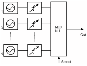
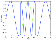
In "phase coherent switching" mode, phase information for arbitrary many frequencies is preserved. The equivalent circuit diagram is shown in figure 2.2. Each frequency is generated by a dedicated oscillator and phase shifter. Switching between different frequencies is done by just switching the desired oscillator to the output. Figure 2.3 shows an example of the switching cycle ω1 -> ω2 -> ω1 in phase-coherent switching mode. When reverting from ω2 back to ω1, the rf signal's phase is the same the signal at frequency ω1 would have, if one never had switched to a different frequency (here ω2) in between.
 |
 |
 |
| Figure 2.1:
Phase-continuous switching. The phase after switching back to initial frequency is different to the initial phase. |
Figure 2.2:
Equivalent circuit diagram of phase-coherent switching. |
Figure 2.3:
Phase coherent switching. By switching between frequencies the phases of each one is preserved. |
Why not use an Arbitrary Waveform Generator?
An Arbitrary Waveform Generator (AWG) is designed to store a signal in memory that arbitrarily varies with time and to output this time series when triggered. Thus, phase-continuous as well as phase coherent switching is possible in principle using such a device. However, the available memory usually limits the usefulness of an AWG for many experimental applications. This is illustrated here with an example:
One would like to generate a sequence of rf pulses with well
defined frequency, amplitude, and phase around a centre
frequency of 100 MHz, for instance, to modulate laser light
with the help of an acousto-optic modulator. The parameters
characterizing each pulse may also vary during each individual
pulse, for instance the amplitude may have a desired envelope,
or the frequency is swept, or the phase varies with time in a
prescribed way.
If an AWG is used with the capability to generate an arbitrary
waveform with a bandwidth ranging up to 100 MHz, at a sample
rate of 1 GS/s, and can store up to 16 KB in memory, then one
may generate a single pulse, or a sequence of pulses with
negligible pauses between individual pulses, having a total
length of 8 μs (at 16-bit resolution). Therefore, if the next
pulse (or pulse sequence) needed in a given experiment is
different from the previous one, this has to be loaded into the
AWG's memory every 8 μs which is often not possible.
The VFG-150 places no such restrictions on pulses and pulse sequences. Its particular way of handling data and generating a desired waveform lets the user create (almost) any pulse sequence of arbitrary length where each pulse has a desired frequency (up to 150 MHz), amplitude, and phase (these parameters, of course, may vary during a given pulse).
Examples for applications
Trapped ions:
- U. G. Poschinger et.al., J. Phys. B: At. Mol. Opt. Phys. 42 154013 (2009)
- N. Timoney et.al., Phys. Rev. A 77 052334 (2008) [QIS21]
- C. Wunderlich et.al., J. Mod. Opt. 54 151 (2007) [QIS19]
Neutral atoms:
- C. Ospelkaus and S. Ospelkaus , J. Phys. B 41 203001 (2008)
- C. Ospelkaus et.al., Phys. Rev. Lett. 97 120402 (2006)
